
- What is SPI?
SPI is the abbreviation of Serial Peripheral Interface. It is a synchronous serial interface technology launched by Motorola. It is a high-speed, full-duplex, synchronous communication bus. - Advantages of SPI
Supports full-duplex communication
Simple communication
High data transmission rate - Disadvantages of SPI
There is no specified flow control, no response mechanism to confirm whether the data is received, so compared with the IIC bus protocol, there are certain defects in data reliability. - Characteristics of SPI
High speed, synchronous, full-duplex, non-differential, bus-type
Master-slave communication mode 2): - Detailed explanation of protocol communication timing
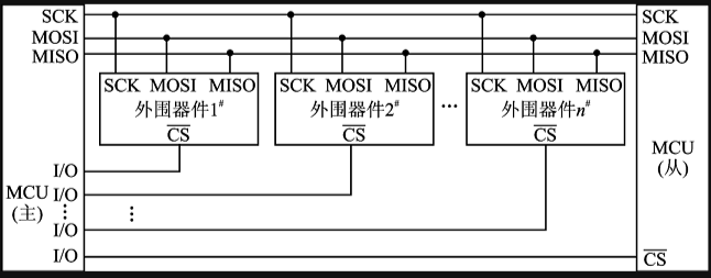
1): The communication principle of SPI is very simple. It works in master-slave mode. This mode usually has a master device and one or more slave devices, requiring at least 4 wires. In fact, 3 wires are also acceptable (for unidirectional transmission). It is also common to all SPI-based devices. They are SDI (data input), SDO (data output), SCLK (clock), and CS (chip select). (1) SDO/MOSI-master data output, slave data input; (2) SDI/MISO-master data input, slave data output (3) SCLK-clock signal, generated by the master device:
(4) CS/SS-CS controls whether the chip is selected, that is, only when the chip select signal is a pre-defined enable signal (high voltage or low voltage), the operation of this chip is effective, which allows multiple SPI devices to be connected on the same bus. It should be noted that in specific applications, when multiple devices are connected to an SPI bus, the CS of the SPI itself may be replaced by other GPIO pins, that is, the CS pin of each device is connected to a different GPI0 on the processor side, and the specific SPI device to be operated is controlled by operating different GPIO ports, reducing interference between various SPI devices.
SPI is a serial communication protocol, that is, data is transmitted one bit at a time starting from the MSB or LSB, which is why the SCK clock line exists. The SCK provides a clock pulse, and MISO and MOSI complete data transmission based on this pulse. SPI supports 4-32 bits of serial data transmission, supports MSB and LSB, and needs to reset the SPI Master’s big and small ends when the big and small ends of the slave device change during each data transmission.
2): It should be noted that our SPI communication has 4 different modes. Different slave devices may be configured to a certain mode at the factory, which cannot be changed; but our communication parties must work in the same mode, so we can configure the SPI mode of our master device and control the communication mode of our master device through CPOL (clock polarity) and CPHA (clock phase), as follows:
Mode0: CPOL=0, CPHA=0
Mode1: CPOL=0, CPHA=1
Mode2: CPOL=1, CPHA=0
Mode3: CPOL=1, CPHA=1
Clock polarity CPOL is used to configure the SCLK level in which state is idle or valid. Clock phase CPHA is used to configure the edge at which data is sampled:
CPOL=0, indicating that when SCLK=0, it is in idle state, so the effective state is when SCLK is at a high level.CPOL=1. Indicates that when SCLK=1, it is in idle state, so the effective state is when SCLK is at a low level.CPHA=0, indicating that data sampling is at the first edge, and data transmission is at the second edge.
CPHA=1, indicating that data sampling is at the second edge, and data transmission is at the first edge.
For example:
CPOL=0, CPHA=0: At this time, in idle state, SCLK is at a low level, and data sampling is at the first edge, that is, SCLK jumps from a low level to a high level, so data sampling is on the rising edge, and data transmission is on the falling edge.
CPOL=0, CPHA=1: At this time, in idle state, SCLK is at a low level, and data transmission is at the second edge, that is, SCLK jumps from a low level to a high level, so data sampling is on the falling edge, and data transmission is on the rising edge.
CPOL=1, CPHA=0: In idle state, SCLK is at high level, data acquisition is on the first edge, that is, SCLK jumps from high level to low level, so data acquisition is on the falling edge, data transmission is on the rising edge,
CPOL=1, CPHA=1: In idle state, SCLK is at high level, data transmission is on the second edge, that is, SCLK jumps from high level to low level, so data acquisition is on the rising edge, data transmission is on the falling edge.